SRT 4120 - TV STRONG - Free user manual and instructions
Find the device manual for free SRT 4120 STRONG in PDF.

User questions about SRT 4120 STRONG
0 question about this device. Answer the ones you know or ask your own.
Ask a new question about this device
Download the instructions for your TV in PDF format for free! Find your manual SRT 4120 - STRONG and take your electronic device back in hand. On this page are published all the documents necessary for the use of your device. SRT 4120 by STRONG.
USER MANUAL SRT 4120 STRONG
2000 Channels TV and Radio channels
- 6 languages menu system (English, German, French, Italian, Spanish, Polish). Other language sets, SET 2 (English, Czech, Croatian, Hungarian, Slovak, Romanian) and SET 3 (English, Dutch, Turkish, Russian, Portuguese, Bulgarian), available to download over the air and on company web site.
- Multiple Favourite Channel Lists (Favourite 1, 2, 3, 4)
- Channel Lock
- DVB Present/Next event information (EPG)
- 5 timers for recording or as a sleep timer
- 3 timer modes: daily, weekly, once
- Parental lock at box and menu levels
Automatic search for all digital transponders in the antenna
- Support DiSEqC 1.2 up to 32 satellites
- Selectable audio channel on audio outputs : Stereo, left or right
- Multi language audio support (up to 25)
- Teletext function support (VBI reinsertion)
- Software update via scart
- Reset to factory settings function
- Loop through VPS signal for VCR recordings (in Standby mode)
C and Ku Band reception
- LNB Control: Horizontal / Vertical polarity switching (18/13V +/- %7,5), 0-22 kHz switching, toneburst A/B switching for dish selection, DiSEqC 1.0
- Pre-installed FTA channels for Astra and Hotbird satellites
- Signal strength bar and C/N estimator for antenna adjustment
- Various channel search options
- Satellite search for preset transponders
- Transponder search
- Single channel search
- Network search
- Automatic search for newly added transponders
-
FTA search option for satellite and auto search modes
-
Auto FEC search,
-
Auto PID correction, (except user defined PIDs)
- Auto channel name correction
Audio mute and volume control
CD Quality Sound
English
Zero-IF digital tuner
Frequency Range
:950\~2150MHz
Input Signal Level
-25\~-65dBm
- Digital Decoding Properties
Demodulation
: QPSK and FEC for 2~45 Msps, SCPC/MCPC compatible
Video Decoding
:MP@ML,PAL/NTSC,4:3/16:9
Video Out
:PAL
Audio Decoding
: MPEG Layer I & II, 32/44.1/48 KHz sampling frequencies, single/dual channels, stereo & joint stereo
- System switching (TV/RADIO)
- Last watched channel saving
- LNB short circuit and overload protection by software
- IR remote control
Less than 7W power consumption in standby mode
2. SAFETY PRECAUTIONS
Please read the following recommended safety precautions carefully for your safety.
2.1. POWER SOURCE
The receiver should be operated only from a 230 VAC, 50 Hz outlet. Please do not open the cover by yourself. There is high voltage in the set, which will danger your life. Please ask the closest service for help.
2.2. POWER CORD
The power supply cord should be placed so that they are not likely to be walked on or pinched by items placed upon them or against them. Pay particular attention to cord where they enter the plug, power outlet, and the point where they exit from the receiver.
2.3. LIQUIDS
Keep liquids away from the receiver. The receiver shall not be exposed to dripping or splashing and no objects filled with liquids, such as vases, shall be placed on the apparatus.
2.4. SMALL OBJECTS
Coins or other small objects must be kept away from the receiver as they can fall through the ventilation slots of the receiver and cause serious damage.
2.5.CLEANING
Disconnect the receiver from the wall socket before cleaning it. Use a dry cloth lightly dampened (no solvents) to clean the exterior of the receiver.
2.6. VENTILATION
Minimum distance of 10cm, from both sides and a distance of 15cm, to upwards around the apparatus should be kept for sufficient ventilation. Take care for a good air circulation. The ventilation slots should not be impeded by covering the ventilation openings with items such as newspaper, tablecloths, soft furnishings, curtains, carpets, etc.
2.7.CAUTION
- Please do not place the set and remote control under direct sun light.
- The set should be placed on a solid and safe base.
- The location should not be selected as a room with high humidity, as the condensation, arising in the kitchen for example, may cause malfunction or damage the set.
- Heating or other thermal radiations under the set also may cause malfunction or damage the set.
- The hot air, which arises during the operation, should be ventilated with sufficient air circulation. Please do not put the set into closed areas and do not cover it.
- Please avoid the contact of the set and remote control with water or humidity. Do not put into operation near bath, swimming pools.
- Connect the power supply of the receiver only after the installation is ready.
- The parabolic antenna has to be grounded correctly. For this you have to follow the appropriate VDE regulations.
- Take care to provide good air circulation. Place the receiver in a location with adequate ventilation to prevent heating up of the receiver.
- No naked flame sources such as lighted candles should be placed on the apparatus.
- Never stack other electronic equipment on top of the receiver.
- Remove batteries from remote control when it is not to be used for a long period. Otherwise it can be damaged due to any leakage of batteries.

The lightning flash with arrow head symbol, within an equilateral triangle, is intended to alert the user to the presence of uninsulated "dangerous voltage" within the product's enclosure that may be of sufficient magnitude to constitute a risk of electric shock to persons.
WARNING
DO NOT OPEN RISK OF ELECTRIC SHOCK
CAUTION: TO REDUCE THE RISK OF ELECTRIC SHOCK, DO NOT REMOVE SCREWS. NO USER SERVICEABLE PARTS INSIDE. REFERServICINGTO QUALIFIED SERVICE PERSONNEL.

The excclamation point within an equilateral triangle is intended to alert the user to the presence of important operating and maintenance (servicing) instructions in the literature accompanying the appliance.
3.PREPARING
3.1. SATELLITE ANTENNA
To have an excellent function of your digital set-top box, it is necessary to install the antenna correctly. Please avoid under all conditions to have a short circuit at the antenna cable conductors (LNB receivers). Your digital set-top box is equipped with a LNB short-circuit protection.
3.2. REMOTE CONTROL
First open the battery cover on the underside of the remote control. Put on both batteries 1.5Volt (R03/AAA) referring to the imprinted symbols (+/-) in the battery case and put on the battery cover again.
While using the remote control, direct it towards the front side of the receiver. If the remote control do not work or the chosen function could not be made, the batteries are most probably exhausted and they should be replaced as soon as possible. Please use only the leak proof batteries. It is the best to take out the batteries from remote unit in case you wouldn't use the remote control unit for long time.
3.3. CONNECTIONS
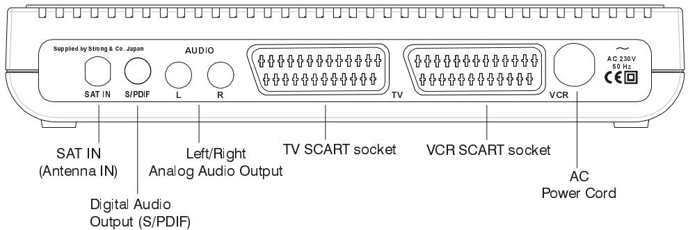
3.3.1. CONNECTION TO THE TV
Connection over scart connector: Connect your set-top box with a scart cable using the TV scart connector on the rear panel to your television's scart connector (the one with RGB input, this is usually the first scart). If you use a scart connector which does not have RGB input, you will not achieve the high performance of your digital set-top box since your TV will use composite video signal instead of the RGB signals.
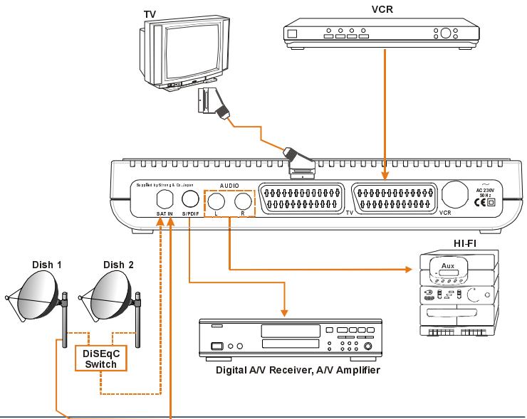
See Diagram 1 (Page 35)
3.3.2. CONNECTION TO SATTELLITE ANTENNA
Carefully plug in the connectors of the satellite antenna cables to the terminal of your set-top box labeled as LNB. See Diagram 1 (Page 35)
3.3.3. VCR SCART CONNECTION
1) Connect one end of Scart cable to TV Scart connector on the STB and the other end of to a Scart connector on your TV
2) Connect one end of Scart cable to VCR Scart connector on the STB and the other end of to a Scart connector on your VCR
- When the receiver is in standby mode:
When connected device (i.e., DVD, VCD) is switched on, the device will be automatically routed to TV.
- When the receiver is on:
When connected device (i.e., DVD, VCD) is switched on, the device will be automatically routed to TV. Otherwise the receiver will remain routed to TV. By pressing "0" button on the remote control receiver is routed back to TV manually.
Some devices which is connected to receiver do not support this feature. In this case routing process is done manually; connected device is routed to TV by pressing "0" button on the remote control provided that no menu on the screen. Then TV is switched to AV mode manually. By pressing "0" button again receiver will be routed back to TV.
See Diagram 2 (Page 35)
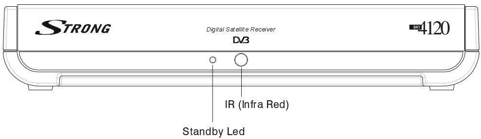
4. FRONT PANEL AND BACK PANEL
FRONT PANEL
BACK PANEL
- REMOTE CONTROL
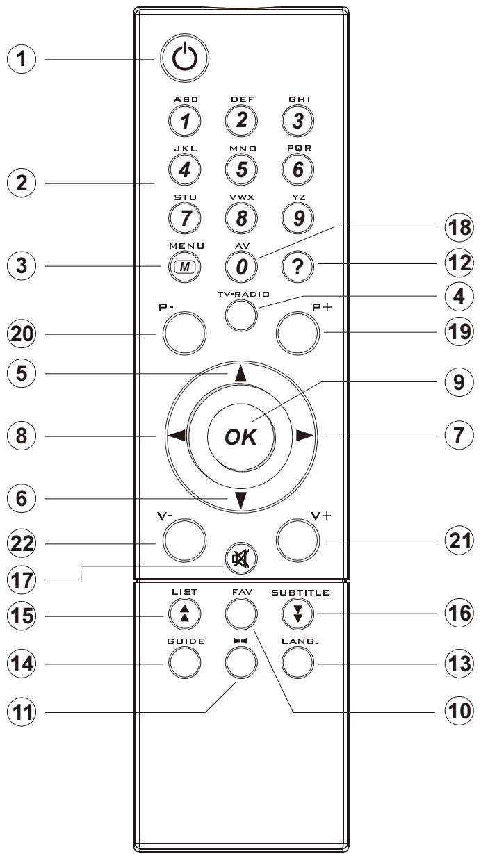
5.1 REMOTE CONTROL FUNCTION
- STANDBY ON / OFF
- DIGITS & LETTERS
- MENU
- TV/RADIO
- CURSOR UP (^+)
- CURSOR DOWN (P-)
- CURSOR RIGHT (V+)
- CURSOR LEFT (V-)
- OK
- FAVOURITE PROGRAM (BLUE BUTTON)
- AUDIO MODE SELECTION (YELLOW BUTTON)
- INFO/HELP (?)
- LANGUAGE SELECTION (LANG.)
- GUIDE (EPG MENU)
15.PROGRAM LIST/PAGE UP (RED BUTTON) - SUBTITLE / PAGE DOWN (GREEN BUTTON)
- MUTE
18.AV
19.PROGRAMUP (P + )
20.PROGRAMDOWN(P-) - VOLUME UP (V+)
- VOLUME DOWN (V-)
5.2. STANDBY ON / OFF
After making cable connections, the receiver goes out of stand-by mode. After getting out of stand-by mode, the receiver tunes immediately to the last watched/listened channel.
When the "STANDBY ON/OFF" key on front panel is pressed, it goes directly to the stand-by mode.
5.3.MENU
By pressing MENU key on the remote control, main menu is accessed, MENU key will be also used to go out of the menus (Channel Organiser, channel list, electronic channel guide...) to no menu or go out of the submenus to upper menu.
"▲" and "▼" are used to move up and down in the menus to access the submenus. OK key on the remote control is used to enter the submenu selected.
5.4. TV/RADIO TOGGLE (EXIT)
When the TV/RADIO key is pressed either on the remote control, the receiver changes mode (from TV to Radio or from Radio to TV). When the mode is changed, receiver tunes to the last watched / listened channel. In Radio mode, if display is available, point at the end of 4 digit display glows.
There are special TV and Radio icons in the channel banner and channel info OSD.
TV/RADIO key will be also used to get out of the menus and submenus to no menu.
5.5.PROGRAMUP/DOWN
When "CHANNEL (CURSOR) UP/DOWN" key is pressed either on the remote control or on the front panel, the receiver tunes to the next (respectively previous) channel in selected channel mode (in the channel organiser, channel list or electronic channel guide menus, it tunes the channel after OK key is pressed). If a channel that will be tuned is locked, the user must enter the password. If a wrong password is entered, (a banner will not warn the user) it can not tune the desired channel, it can tune to the previous or next channel by pressing P- and P+ keys respectively.
5.6. VOLUME UP / DOWN
When V + or V - is pressed, either on the remote control or on the front panel, a banner is displayed, which shows graphically the present volume. The sound is increased or decreased by moving the cursor on volume scale by pressing V + and V - keys respectively.
5.7. LIST / PAGE UP (RED BUTTON)
When the LIST key is pressed whole channel list or one of 4 favourite lists is displayed. If the last watched/listened channel is one of the favourite channels then the favourite list in which the last watched/listened channel takes place is displayed.
RED key is also used to display channels page by page in channel table and channel list, also to display the extended event information page by page in electronic channel guide. The upper page is accessed with this key.
5.8.AUDIO MODE SELECTIONS (YELLOW BUTTON)
The YELLOW key (LRS) will toggle the sound mode. The mode is stereo as default. If the user wants to listen to only the left or right audio channel, the sound mode can be changed with this key. On single sound channel modes (left or right channel) same sound channel will be switched to both left and right outputs. When the mode is changed an appropriate OSD will be displayed for a while. And this will be stored for this channel to be able to switch to requested audio mode next time.
5.9 INFO / HELP (? BUTTON)
When INFO (?) key is pressed an informative menu OSD is displayed. It gives information related to currently watching channel. This info includes channel number, channel name, channel mode (TV or Radio), transponder name, transponder frequency, favourite list name (if the channel is one of the favourite channels), audio mode, whether the channel has teletext or not and short event description, additionally audio, video, and PCR PID values of the channel.
INFO key is also used to show help window which describe some remote control functions in the menus according to the menu function.
This help window must be closed (by pressing INFO key again) to be able to perform the options in the menu.
5.10. LANGUAGE KEY (MULTI AUDIO SERVICES)
The LANG key allows selecting another sound track of the present channel. When the language key is pressed a menu is displayed showing the number of possible audio languages for TV and tracks for Radio channel available. The user is allowed to navigate using P+, P- keys and select with OK key. If an audio language support Dolby digital output, "AC3" expression is seen at the end of the audio language name. If the channel does not have multi audio, a pop-up message will warn the user.
5.11. GUIDE KEY (ELECTRONIC PROGRAM GUIDE)
If the GUIDE key is pressed electronic channel guide (EPG) menu is displayed. This menu shows firstly the current and by toggling (LEFT/RIGHT) the next events' information (start and end time for current and next events, channel no, channel name, event name of the channels in tuned transponder).
This menu consists of a channel bar which shows time scale from current time to 3 hours + current time. This bar shows current/next event period in current/next event mode as highlighted.
There is also an option for every channel to make user aware that the next event starts, which is "reminder". If the reminder is set (by pressing OK key in next event mode - the clock symbol near the time scale will become highlighted.) When that event's start time is reached, a pop up message will appear and if the user accepts to change the channel, receiver will switch to that channel.
5.12. FAVOURITE CHANNEL (BLUE BUTTON)
Each channel can be selected as favourite from the channel organiser menu; the user goes on the channel wanted to mark as favourite, then "Favours" is selected by pressing "▶" key. The desired channel is added to one or several of 4 independent Favourite lists by pressing OK button on the selected favourite. When Favourites frame is activated, FAV button toggles between the favourites. The limit for the number of favourite channels is 100.
In no menu mode, pressing FAV (blue button) on remote control will cause the receiver to change the current channel to the first favourite channel. The user can select any channel in current favourite list by toggling (pressing "▲" and "▼" keys) and other favourite lists by pressing FAV button again. If there is no channel in any favourite list a warning message is displayed on screen.
If a channel has been locked by the lock code, the user must input the password. If a wrong password is entered (a banner will not warn the user) the desired channel can not be watched and the previous or next favourite channel can be watched by pressing P- and P+ keys and next favourite lists can be selected by pressing FAV button again.
FAV button must be pressed one more time to get out of favourite channels.
5.13. SUBTITLE / PAGE DOWN (GREEN BUTTON)
When the user presses SUBTITLE key, a menu OSD is displayed with language of default or first subtitle coming from transmission. The language of subtitle can be changed from this menu by toggling. If there is no subtitle in that channel, "None" is displayed in this menu. After the user selects any of them, it starts to display the appropriate subtitle on the screen. Selecting "None" from the subtitle menu, disables subtitle display.
This Green key is also used to display channels page by page in channel table and channel list, and also to display the event information page by page in electronic channel guide. The next page is accessed with this key.
5.14.MUTE
When the MUTE key is pressed, mute symbol is displayed on the right side of the screen. The mute symbol will stay until MUTE is pressed again, or V + V- keys is pressed. Mute function does not work in case of Dolby Digital (AC3) output.
The mute symbol is not displayed on the screen in case of any menu displayed.
6. MENU INTERFACE
6.1. FIRST TIME INSTALLATION
When the box is opened from stand-by and there is no channel stored in database, First Time Installation Menu window is displayed on the screen. In six languages it writes, "Welcome! Please select your language". The appropriate box language can be chosen by highlighting the desired language (with " ", " " keys) and pressing OK.
Welcome! Please select your language.
After pressing OK, Antenna Installation Menu will be displayed. After you set the correct parameters as explained in the Antenna Installation Menu, go to the Start Scan line and press OK.

Then choose "Yes" for "Start Scan?" The box will automatically find the preset channels and store them.
6.2. MAIN MENU
Main menu is accessed, pressing the MENU key on the remote control.
Main Menu
Channel Organiser
Installation
System Set-up
Timers
The items accessed through the main menu are:
- Channel Table
- Installation
- System Set-up
- Timers
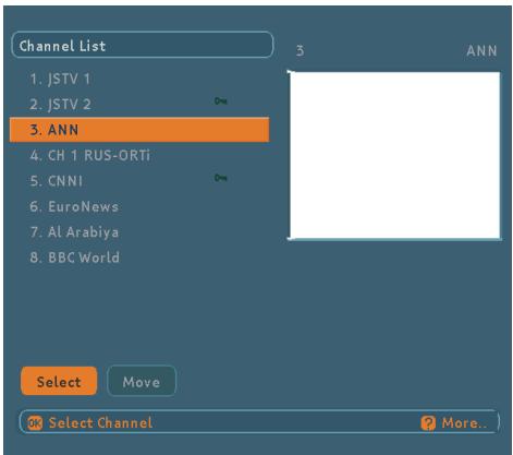
6.3.CHANNEL ORGANISER
Following operations can be performed in this menu:
- Navigating the whole list of channels
- Reordering the list
- Deleting unwanted channels
- Renaming channels
- Adding locks to channels
- Setting the favourite lists
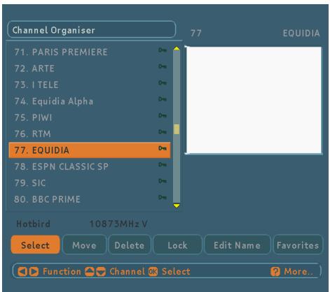
6.3.1. NAVIGATING THE WHOLE LIST OF CHANNELS
While in the channel menu "▲", "▼" (P + / P -) keys serves for moving focus to previous or next channel and Red/Green (LIST/SUBTITLE) keys for page up and page down.
The transponder frequency, polarisation and satellite name of the selected channel are displayed left bottom side of the screen.
To watch a specific channel (highlighted channel), press OK while the "Select" part is highlighted. Then the selected channel will be displayed in the right-top corner of the screen.
The scroll bar in middle of the screen shows relative position of the currently visible channel with respect to the whole list.
6.3.2. REORDERING THE LIST
Reordering can be done by moving the channels one by one to new positions. In order to do that "Move" button is highlighted using keys then channel to be moved is selected by pressing OK, the colour of the channel will be changed to purple. In this state , keys will replace the channel with the previous or next channel. Desired channel location can be typed as number and the channel will be moved to that position (if number entered is greater than the max channel number then it is accepted as the max channel number). After you're satisfied with last position of the channel press OK to finish moving channel. If you want to cancel moving operation press MENU.
6.3.3. DELETING UNWANTED CHANNELS
To delete a channel, highlight it using "▲", "▼" or Red/ Green buttons then highlight the "Delete" button using "←" "→" keys and press OK. A message displayed to confirm your decision, if you still want to delete select "YES" button and press OK once, deleting operation will be cancelled if "NO" option is selected or menu key is pressed.
6.3.4. RENAMING CHANNELS
To rename a specific channel select it, then select the "Edit Name" button using " 一 " /“>” keys and press OK. The name appears now on the right side of the menu with the first character highlighted.
"\"/\"" keys moves to the previous/next character. "▲", "▼" keys toggles the current character, i.e., b character becomes c with "▲" and a with "▼". The numeric buttons from "0" to "9" replaces the highlighted character with the character that corresponds to selected numeric. The limit for the channel name is 15 character.
In this editing mode pressing Menu cancels the editing and pressing OK saves the new name of the channel.
6.3.5. ADDING LOCKS TO CHANNELS
Channel locking provides a password-protected access to channels selected by parents. In order to lock a channel you should know the parental Lock password (default password is 0000), then highlight the channel to be locked and select the "Lock" button, when OK is pressed a password dialog is displayed. Enter the parental lock code, press OK and then Lock icon will be displayed in front of the selected channel. Repeat the same operation to cancel the Lock.
If you forget the password you can use the universal password (8277). Password can only be changed from the Configuration Menu.
6.3.6. SETTING THE FAVOURITE Lists
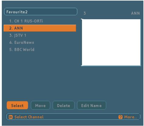
Favourite lists provide an easy way to group channels. Four favourite lists are available as Favourite1, Favourite2, Favourite3 and Favourite4. The names of the favourite lists can be changed from the List menu. In the Channel Table menu the channels can only be added or removed from a specific favourite list. Reordering the channels in a favourite list can only be done from the favourite list menu.
In order to add or remove a channel from a favourite list, highlight the "Favours" button using 14 keys, the favourite submenu will be displayed. Then select the channel to be added/removed to/from the favourite list using "▲", "▼" or Red/Green buttons, choose the favourite list name (in which the channel will be added) from the list menu by using the FAV key then press OK. The favourite channel icon will be displayed or removed in/from the selected channel bar. Pressing Menu key saves all your settings.
If you want to add that channel to Favourite2,3, or 4, you should press FAV button in order to navigate through favourite option. Then press OK button.
6.4. INSTALLATION MENU
Installation
advanced
Antenna Installation
First Time Installation
Add New Channels
Factory Settings
The Installation menu mainly intends to help you for setting your antenna configuration and building a Channel Table into your receiver in most efficient way.
This menu includes:
- Antenna Installation
- First Time Installation
- Add New Channels
- Factory Settings
6.4.1.ANTENNA INSTALLATION MENU
It is an advanced type menu and helps you to set & store your antenna configuration to appropriate satellite (ASTRA, HOTBIRD...). Antenna Installation menu shows all stored satellites with their names and configurations. There are totally 32 satellites -some are presets-, you can edit & store or scan any satellite by using dedicated keys.
After entering Antenna Installation menu, the following parameters is displayed:
Satellite Name (Preset names and others): Currently 27 preset satellites exist as Astra, Hotbird...etc. and 5 user defined satellites as User1...User5 append to them. The satellites can be renamed by remote control.
Low Frequency: You should set this value according to low oscillator frequency of your LNB device (by default 9750 for Universal LNB).
High Frequency: You should set this value according to high oscillator frequency of your LNB device (by default 10600 for Universal LNB).
Polarisation: You can select antenna polarisation as Horizontal, Vertical or both (H/V).
22 kHz: You can select frequency band as low or high by choosing Off or On respectively. If you select Auto, receiver decides 22KHz On or Off depending on frequency.
DiSEqC (Off / Tone A / Tone B / DiSEqC 1 / DiSEqC 2 / DiSEqC 3 / DiSEqC 4); You should set this according to switch position of the desired satellite; if your LNB device is connecting directly to your receiver we advise you to select Off mode.
LNB Power: You can enable/disable LNB supply, this must be set to On if the receiver is not connected to other box via loop- through.
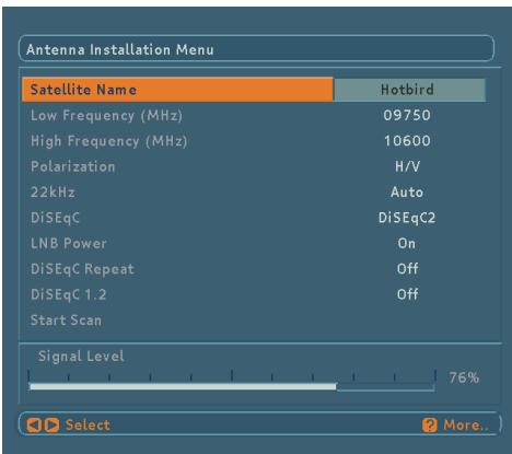
Except satellite name, all parameter values are dependent to satellite name so when you toggle this button, the whole parameters are updated automatically. To give an idea about the signal level, or you can say power level, there is a Signal Level indicator in this menu. It updates after you change any parameter. For all items operation is the same, after highlighting the item and change value by toggling (by pressing 14 / 12 keys).
After pressing "Start Scan" the user will be asked whether he would like to start scan or not? By pressing OK, all channels and channels (predetermined in database) of that satellite will be searched and stored into receiver, this operation is called as "Preset Search".
6.4.2. FIRST TIME INSTALLATION
It is an advanced type menu. A "Welcome!" window appears on the screen after warning message to ask to user whether he wants to delete all channels (To delete all channels means clearing the database) or not, this window includes welcome messages in all languages and user selects the language. Then Antenna Installation Menu is displayed and the user selects the satellite name and other specifications to find out channels. After pressing "Start Scan" the values entered are stored to that satellite. And the user will be asked whether he would like to start scan or not? By pressing OK, all channels (predetermined in database) of that satellite will be searched and stored into receiver and channel table is updated.
6.4.3. ADD NEW CHANNELS
After highlighting the Add New Channels by pressing up/down keys, press OK button or right key.
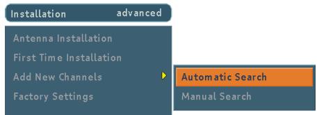
This menu includes:
- Automatic Search
- Manual Search
6.4.3.1.AUTOMATIC SEARCH
The user can scan some or all satellites for only free to air or all channels by this menu. Menu items:
Satellite Name: The satellite selection is made by toggling.
Symbol rate1/2/3: Additional symbol rates for newly added transponders are entered directly by "0,1,2,...9" keys.
For every well-known satellite like ASTRA, HOTBIRD... there is a symbol rate table, which is formerly stored into receiver. So the scan function is performed according to this table or additional symbol rates if there exist.
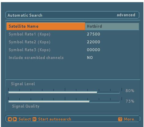
After search, if new channels are found, they are added to the channel table.
6.4.3.2. MANUAL SEARCH
It is an advanced type menu. Menu items:
- Satellite Name
- Polarisation
- Frequency
-
Symbol rate
-
Network Search
-
PID Entry (for single channel search)
Satellite Name, Polarisation values and Network Search requirements are changed by toggling. Frequency and Symbol Rate are entered directly using "0,1,2,...,9" keys.
Video, Audio and PCR PIDs of the desired channel can be also entered by PID Search menu is selected. Every channel has its own PID values, so by entering PID values, only one channel can be find. By pressing OK, the values are stored and after searching if a new channel exists they are appended to the Channel Tables. Found channel name is shown as Pgm.
As soon as entering transponder frequency, changing appears in the signal strength bars (Signal Level and Signal Quality bars) at the bottom of the menu. Signal Level bar shows the strength of the digital signal. Signal Quality bar shows lock quality of the device for entered values.
If Network Search item selected as YES, the parameters of all transponders will be collected from NIT (Network Information Table) and the tuning will be performed.
When tuning in the screen there will be shown the satellite name and frequency, polarization, symbol rate of the current transponder under the found programs.
As shown below there will also be displayed a progress bar which indicates the percentage of searched transponders.
If include scrambled channels item selected as YES, scrambled channels will be also searched. Otherwise only FTA channels will be searched.
6.4.4. FACTORY SETTINGS
The user can use this item to load preset channel table and default settings, which had been loaded to receiver at the factory. To start factory settings, highlight this item and press OK key. Then a message is displayed to warn the user like "Are you sure to DELETE ALL services and LOAD DEFAULT channel table?" The user can confirm by OK key or abandon by MENU key (or by selecting NO).
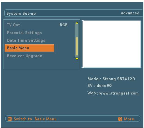
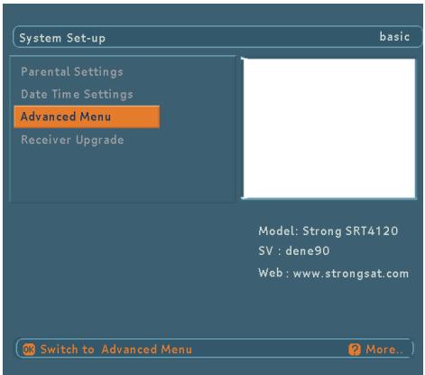
6.5. SYSTEM SET-UP MENU
The user can configure the settings of the box. Select System Set-Up from Main Menu and press OK to enter this menu. There are two modes: Basic & Advanced. If the advanced menu is active, by selecting "Basic Menu" basic menu can be made active or vice versa.
System Set-Up Menu includes the following main items:
Basic Mode
Parental Settings
Date Time Settings
Advanced Menu
Software Version V1.0.0
Advanced Mode
Menu Language
Audio Language
Subtitle Language
TV Type
TVOut
Parental Settings
Date Time Settings
Basic Menu
Software Upgrade
Software Version V1.0.0
6.5.1. MENU LANGUAGE
It is the language used in Menus. By pressing "▲" / "▼" keys Menu Language option is highlighted. The current menu language can be changed and updated by "←"/"▶" keys.
6.5.2.AUDIO LANGUAGE
By pressing "▲" / "▼" keys Audio Language option is highlighted. The current audio language can be changed and updated by "▲"/"▼" keys. Changes will be updated while exiting System Set-up Menu. When new channels are added, they are recorded with the default audio language in database.
6.5.3. SUBTITLE LANGUAGE
By pressing "▲" / "▼" keys Subtitle Language option is highlighted. The current subtitle language can be changed and updated by "▲"/"▼" keys. Changes will be updated while exiting System Set-up Menu.
6.5.4. TV TYPE
By pressing "▲" / "▼" keys TV Type option is highlighted. TV aspect ratio can be changed using "▲" / "▼" keys. TV aspect ratio can be selected between 4:3 or 16:9.
6.5.5. TV OUT
By pressing "▲" / "▼" keys TV Out option is highlighted. The current TV Out type can be changed and updated by "▲" / "▼" keys. The picture quality in RGB is better than CVBS.
6.5.6. PARENTAL SETTINGS
By pressing "▲" / "▼" keys Parental Settings option is highlighted and by pressing OK it is selected. The password container to enable the Lock Code is displayed. Factory default password is set to value "0000". If the password is entered correctly, Parental Settings Menu is displayed including following items:
- Child Lock
- Menu Lock
- Change PIN
| Child Lock | Disabled |
| Menu Lock | Disabled |
| Change PIN |
6.5.6.1. CHILD LOCK
The user can set/reset Child Lock by selecting Enabled/ Disabled. If the Child Lock is enabled, unwanted users can't use the front panel buttons. To be able to use the front panel buttons, Child Lock must be disabled again.
Changes will be updated after exiting MENU.
| Child Lock | Enabled |
| Menu Lock | Disabled |
| Change PIN |
6.5.6.2. MENU LOCK
The user can set/reset Menu Lock by selecting Main Menu / Installation / Disabled. If the Menu Lock is disabled, all menus are unlocked. If the Main Menu option is selected, Main Menu can not be accessed. If the Installation option is selected, Installation Menu can not be accessed. To access the desired menus, correct password must be entered.
| Menu Lock | Main Menu |
or
| Menu Lock | Installation |
6.5.6.3.CHANGE PIN
The password can be changed by selecting Change PIN option. After pressing OK button new password menu is displayed. New password is entered using "0,1,2...9" keys. The new password must be confirmed for security.
If both passwords are four digits long and the same, password is changed.
It is updated after exiting Parental Settings Menu.
If you forget the password, you can enter locked channels and menus and change password by using the universal password (8277).
6.5.7. DATE TIME SETTINGS
By pressing “▲” / “▼” keys Date Time Settings option is highlighted. By pressing OK Date Time Settings Menu displayed, it includes following items:
- Time,
- Date,
- Offset UTC(h).
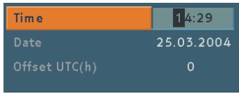
The actual date as day, month and year; time as hour and minute; UTC as hour are entered. After first booting of the box the values are "00:00 / 01.01.2001 / 0" and the actual time, date, and offset to Universal Time Coordinated (UTC) can be entered by " 一 " /“” and ^ 一 0 , 1 , 2 , , 9 " keys.
After first booting the receiver, as soon as get the UTC time from the Satellite, updates the time. The user doesn't have to enter the time settings manually.
6.5.7.1 TIME
By pressing “▲” / “▼” keys Time option is highlighted and actual time can be entered by NUMBER keys. The time entered must be valid otherwise digits are skipped. By pressing MENU key to return System Set-up Menu, time is updated.
6.5.7.2. DATE
By pressing "▲" / "▼" keys Date option is highlighted and current date can be entered by NUMBER keys. The Date entered must be valid otherwise digits are skipped. By pressing MENU key to return System Set-up Menu, date is updated.
6.5.7.3. OFFSET UTC(H)
By pressing / keys Offset UTC(h) option is highlighted and time offset can be toggled with / keys. Time offset will be changed just after the offset is toggled. Time will be also updated according to the new time offset. By pressing MENU key to return System Setup Menu, time and offset UTC(h) is updated.
6.5.8.ADVANCED/BASIC MENU
By pressing “ ”/“ ” keys Basic Menu / Advanced Menu option is highlighted and by pressing OK, if the advanced menu is active, basic menu will be made active and vice versa.
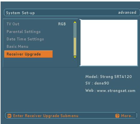
6.5.9. RECEIVER UPGRADE
By pressing OK Receiver Upgrade menu is entered. Detail information about Receiver Upgrade Menu is in section 6.9.2
6.6. TIMER MENU
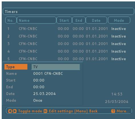
By pressing “▲” / “▼” keys in Main Menu, Timers is highlighted and by pressing OK, Timer Menu is entered. There is a five column summary information, such as timer no, channel name, start time, end time, start date and mode, for each of the five timers.
There are two ways to set a timer. If the Start/End time and Date are valid values, the timer can be set directly by changing the mode to "Active" from "Inactive" using ' / ' keys.
If the Start / End times and Date are invalid or if the set values will be changed totally, OK must be pressed while the desired timer is highlighted in the summary list. A new window where the timer details will be entered is displayed on the lower part of the screen. The timer details are as follows:
Type: By using " 一 " /” keys, channel type, i.e., TV or Radio is selected.
Name: According to the type that is chosen above, 一 " keys will navigate the user through the TV or Radio list and name of the channel is selected.
Start: By using "0,1,2...,9" keys start time of the timer is entered.
End: By using "0,1,2...,9" keys end time of the timer is entered.
Date: By using "0,1,2,...,9" keys date of the timer is entered.
Mode: By using “<”/“>” keys, timer mode is selected as “Once”, “Daily” or “Weekly”.
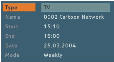
The current time and date are shown on the lower-right part of the screen to help the user.
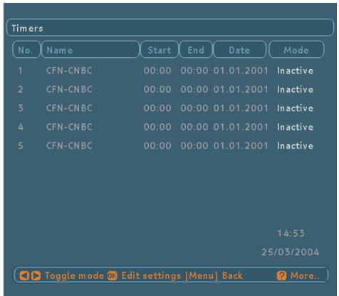
After the desired detail fields are filled, by pressing OK the settings are saved, by pressing MENU new settings are cancelled and the user turns back to timer menu. A Timer setting is cancelled (disabled) by changing the mode to "Inactive" in Timer Menu.
When a timer Start time is reached, the receiver switches to the desired channel, then when the End time is reached, the box goes to stand-by mode. This utility helps the box to be used as a sleep-timer.
6.7.NO MENU
6.7.1. ELECTRONIC PROGRAM GUIDE (EPG)
In no menu mode, by pressing GUIDE button Electronic Program Guide menu (EPG menu) is displayed. All channels in the current transponder in which the current program takes place are displayed. The current program is highlighted. By pressing “▲” / “▼” keys the current program can be changed.
Some programs have some information such as name, start time, end time end short/extended event description of the current and next events.
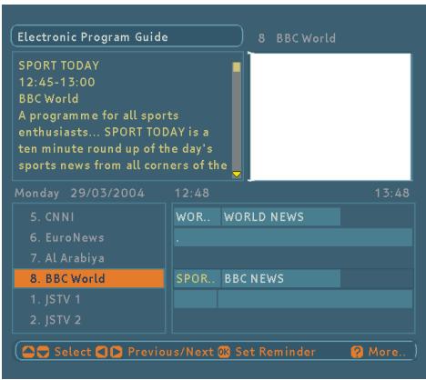
Note that the event information is updated automatically when the current transponder is changed. Therefore, after switching to a new transponder, it takes a few seconds to get all of the data of the programs in new transponder.
If there is no any event information data available on current transponder, only program names are displayed.
By using " 一 " /“》 keys the EPG Menu mode can be changed. (Current Event mode is default.)
6.7.1.1.CURRENT EVENT MODE
By pressing "▲" / "▼" / OK keys watched/listened highlighted channel can be changed. The user can use "▲" or "▶" key to switch to Next Event mode.
Start and Finish time of the current event are displayed at the top of the event box. The current event information is displayed in the event box. Red/Green buttons can be used to scroll up/down. Yellow/Blue buttons can be used to read the information line by line.
At the right bottom of the screen, current and next event duration are displayed on an 3-hour time scale. The highlighted part (yellow) is for the current event.
6.7.1.2. NEXT EVENT MODE
By pressing "▲" / "▼" / OK keys watched/listened highlighted channel can be changed. The user can use "▲" or "▼" key to switch to Current Event mode.
Start and Finish time of the next event are displayed at the top of the event box. The next event information is displayed in the event box. Red/Green buttons can be used to scroll up/down. Yellow/Blue buttons can be used to read the information line by line.
At the right bottom of the screen, current and next event duration are displayed on an 3-hour time scale. The highlighted part (yellow) is for the next event.
There is also an option for every channel to make user aware that the next event starts, which is "reminder". If the reminder is set (by pressing OK key in next event mode - the clock symbol near the time scale will become highlighted-) when that event's start time is reached, a pop up message will appear and if user accepts to change the channel, receiver will switch to that channel.
6.7.2. MESSAGES
If a channel is scrambled or has no video signal "Service is not running or scrambled" message is displayed on the screen (after the program information window disappears).
Service is not running or scrambled
If a channel has no Video signal "Service is not available" message is displayed on the screen (after the program information window disappears).
When the box receives no signal (i.e., the antenna cable is disconnected), "NO SIGNAL" message is displayed on the screen.
NO SIGNAL
When there is a short circuit in LNB, "LNB Overload!!" Please unplug the receiver" message is displayed on the screen.
LNB Overload !!! Please unplug the receiver ...
When there are no channels stored in the box, Timer Menu, Channel List and Channel Table are not accessible. Channel navigation is not possible either. Therefore "First Add new Channels!" message is displayed on the screen.
First Add new Channels!
6.7.3. CHANNEL NAVIGATION
There are two ways to navigate through the channels:
6.7.3.1. P+/P-KEYS
Pressing 广 ^ 一 / ^ (P + /P - ) keys will help the user to go to the next or previous channel in the list.
Please note that, channel navigation using “▲”/“▼” keys is done within the defined list, i.e. within the elements of the Favourite1, 2, 3, 4 lists or complete list for TV and Radio channels. If Favourite1 list is chosen with the Blue button and the box is in TV mode, then “▲”/“▼” keys will switch to the next/ previous channel in the TV Favourite1 list. If Favourite1 is chosen with the Blue button and the box is in Radio mode, then “▲”/“▼” keys will switch to the next/ previous channel in the Radio Favourite1 list.
6.7.3.2. NUMBER KEYS
Pressing a number key will activate a small digit entry window on the left upper corner of the screen in no menu mode. After a digit is entered, the box will wait for 2 seconds till the user enters another digit. If no digit is entered during 2 seconds, the box will switch to the entered number program.
If a number that is greater than the maximum number of programs is entered, the box will switch automatically to the last program.

Each time the box switches to the desired program, an information window is displayed on the lower part of the screen.

This program information window which appear when program changing includes:
- Current mode (T - TV, R - Radio), channel number & name
- Satellite name
- Channel type symbol (radio/tv) (a red cross on the symbol indicates that the program is scrambled).

- A symbol, indicating whether the program is mono left or mono right.

- Stereo/Mono (S/M) symbol, indicating whether the current program is stereo or mono.

- Subtitle symbol, indicating whether the program has subtitle or not. If there is no subtitle, the subtitle field is empty.

English
- AC3 symbol, indicating whether the current program has a AC3 (Dolby Digital) audio or not. If not, the AC3 field is empty.

- Screen mode (16:9/4:3) symbol, indicating the TV type which is set in system set-up menu.

- Current time (HH:MM)
- Present event information (Start time - End time Event name)
- Favourite field (If the user chose the program from the one of the favourite list, table name of the favourite list will be written. If the program is chosen from the complete list, the right field is blank).
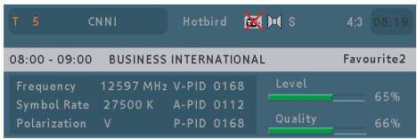
The information banner above for current service includes:
- Transponder Frequency (MHz)
- Symbol Rate (Ksps)
- Polarization (H/V-Horizontal/Vertical)
Video-Audio-Data PIDS - Signal Level and Quality bars
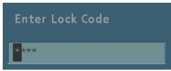
While switching to a locked program, lock code is asked via a window as shown in figure, only after the correct code is entered by using NUMBER keys, switching to this locked program is possible. To skip this channel, P + / P - keys must be used.
6.7.4. VOLUME CONTROL
In no menu mode, by pressing " 一 " /“” keys, a volume banner is displayed, which shows the present volume level graphically. By keeping these keys pressed, the sound can be increased (with "4" key) or decreased (with "3" key).

When the Mute key is pressed, mute symbol is displayed on the upper right side of the screen. The mute symbol will stay until mute is pressed again or V+/V- pressed. Unless there is a menu display, the mute symbol will always be on the screen.
6.7.5. LIST MENU (RED BUTTON)
List Menu is the place where both the whole channel list and the favourite lists are managed. The following operations can be performed in this menu:
- Navigating the current list of channels.
- Reordering the list.
- Removing unwanted channels. (Removing channels from the favourite list only in favourite lists).
- Renaming the favourite names.
When the list menu is displayed by pressing Red key, the channels of the favourite list in which the currently watched favourite channel takes place is displayed. If currently watched channel is not a favourite channel, full list of channels is displayed (radio channels in Radio mode and TV channels in TV mode). The name of the current list can be seen on the top left corner of the menu.
6.7.5.1. NAVIGATION
To watch a specific channel, highlight it using "▲" / "▼" / Red/Green buttons, then press OK while the "Select" button is highlighted. The name and number of the selected channel will be displayed in the right-top corner of the screen.
The scroll bar in middle of the screen shows relative position of the selected channel with respect to the whole list.
6.7.5.2.CHANNEL REORDERING
Reordering can be done by moving the channels one by one to new positions. In order to do that "Move" button is highlighted using 14 / 12 keys, then channel to be moved is selected by pressing OK, the colour of the channel will be changed to purple. In this state 14 / 12 keys will replace the channel with the previous or next channel, also channel location can be typed as number and the channel will be moved to that position (if valid), after you're satisfied with last position of the channel press OK. If you want to cancel moving operation press MENU.
6.7.5.3. DELETING CHANNELS
If you press the list button when you are on a favourite channel, a list, which includes favourite channels appears.
To delete a channel highlight it using "▲" / "▼" or Red/ Green buttons, then highlight the Delete button using "▲" keys and press OK. A message appears to confirm your decision, if you still want to delete then select "YES" and press OK once, deleting operation will be cancelled if "NO" is selected or by pressing Menu key.
Please note that if the current list is a favourite list, the channel is not actually deleted but just removed from that favourite list.
6.7.5.4. RENAMING THE FAVOURITE LIST
If you press the list button when you are on a favourite channel, a list, which includes favourite channels appears.
To change the name of the current Favourite List highlight the "Edit Name" button using 14 = 12 keys and press OK. The name appears now on the right side of the menu with the first character highlighted.
"\"/\" keys moves to the previous/next character. ^ / " keys toggles the current character, i.e., b character becomes c with ^ and a with ^ . The numeric buttons from "0" to "9" replaces the highlighted character with the character that corresponds to selected numeric.
In this editing mode pressing Menu cancels the editing and pressing OK saves the new name of that favourite list.
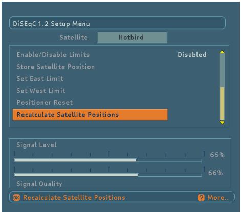
6.8.DISEQC1.2SETUP MENU
DiSEqC 1.2 Setup Menu is located under Antenna Installation Menu. User selects the name of the satellite and its properties like polarisation and frequency band at the Antenna Installation Menu before entering DiSEqC 1.2 Setup Menu.
Setting "Polarisation" and "22 kHz" parameters from Antenna Installation Menu is optional. By default, polarisation is set to "H/V" (both horizontal and vertical frequencies) and 22 kHz is set to "Auto" (both 22 kHz Off and 22 kHz On). These parameters can be left in their default positions to simplify the installation task. The aim is to drive the motor on the polar axis and watch the signal quality indicator. When the receiver is tuned to a satellite, the signal quality bar will rise. If the user is satisfied with the signal quality he stores the current position of the antenna. Otherwise he will try to fine-tune it until the desired level is reached.
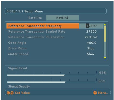
There are a certain number of satellites, which have predefined presets stored in the box. Satellites having predefined presets appear with their original names like Astra, Hotbird, etc. If a satellite has predefined presets, the user does not have to enter a reference transponder from that specific satellite although It is possible to enter a reference transponder for all satellites. Figure shows the upper part of the DiSEqC 1.2 Setup Menu
Satellites that do not have predefined presets appear with names like User 1, User 2, etc. Here, frequency, symbol rate and polarisation of a reference transponder should be entered in order to be tuned into the satellite.
DIGITAL TV
The two essential parameters, frequency and polarisation of a reference transponder should be entered according to the antenna settings (See Figure 6.8.3). If the polarisation setting is vertical in Antenna Installation Menu, it will be vertical in DiSEqC 1.2 Setup Menu automatically and the user will not be able to change it. Same situation is valid when the polarisation is horizontal.
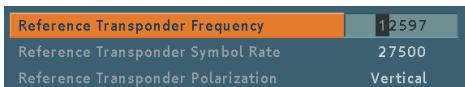
Polarisation should be set to "H/V" from Antenna Installation Menu in order to be able to changed by the user from DiSEqC 1.2 Setup Menu. Frequency values should also be entered according to the 22kHz mode. In "22 kHz Off" mode (Low Band), the frequency range is between 10700 and 11900. It is between 11550 and 12750 for "22 kHz On" (High Band). If 22kHz mode is set to "Auto", the user can enter a value in the whole range that is between 10700 and 12750. Any frequency value out of the specified range will cause a warning message to appear on the screen.
The following part gives a detailed explanation about the DiSEqC 1.2 motor functions.

DIGITAL TV
6.8.1. GOTO ANGLE
Turns the motor to the entered Angle. Enter the angle with digits and use BLUE button to change direction. Press Ok to let it turn. Some Diseq 1.2 positioners do not support go to angle command. If your positioner does not support this function you can enter 000 for the angle in order to turn the positioner to the reference zero position
6.8.2.DRIVE MOTOR
Drives the motor East or West and rotates the antenna on the polar axis. "East" or "West" will continuously blink on the screen to indicate the direction the motor is moving. To drive the motor toward a specific direction, "or" button should be kept pressed.
6.8.3.MOTOR SPEED
Adjusts the speed of the motor. There are two modes, "Fast" and "Slow." "Fast" mode is useful for driving the motor over large angles or coarse adjustment. "Slow" mode comes handy when fine-tuning is needed.
Stores the current location of the positioner as the east limit.
6.8.5. SET WEST LIMIT
Stores the current location of the positioner as the west limit.
6.8.6. ENABLE / DISABLE LIMITS
Enabling the (software) limits will cause the motor not to drive after east or west limit is reached. When the software limits are disabled, the positioner motor will drive over the full (mechanically-defined) arc of its movement.
6.8.7. STORE SATELLITE POSITION
When the desired signal quality is reached, the user can store the current location of the positioner. This functionality enables the Positioner Motor Unit to drive back at any later time to the antenna shaft position stored by the user.
6.8.8. POSITIONER RESET
Restores build in Satellite Table for the positioner Motor Unit.
English
6.8.9. RECALCULATE SATELITE POSITIONS
The positioner motor unit recalculates satellite positions of the other satellites.
6.9. SOFTWARE UPGRADE
6.9.1 SOFTWARE UPGRADE THROUGH TV SCART
The object of this part is to give necessary information and details to the user to upgrade the software of the receiver through scart to RS232 cable (RS232 end for RC, scart for receiver).
The list of the necessary equipment is as follows:
Receiver and TV
PC with "Hyper Terminal" function,
Scart to RS232 cable (RS232 end for RC, scart for receiver).
Steps to be followed by the user are given below:
- Connect the serial communication cable between the RS232 out port of the receiver and the serial communication port (COM1 or COM2) of the PC.
- Make sure that the PC is on.
- Run "Hyper Terminal" channel of the PC from Start / Programs / Accessories / Communications / Hyper Terminal menu.
- For a new connection, run Hypertrm.exe file.
- Give a name and choose an icon for the connection. (You do not need to make a new connection every time. You can use this name for the future connections.)
- Choose communication port in the new coming window (COM1 or COM2) whichever you have used in Step 1.
- Port settings should be as follows:
Bits per second : 115200
DataBits :8
Parity : None
Stop bits : 1
Flow control : None
- Now Hyper Terminal connection is established. From "Transfer" menu, choose "Send File".
- Enter file name to be sent.
-
Choose Xmodem1K as protocol type.
-
Plug in the mains cord of the set to the mains supply just after pressing Send button at the hyper terminal window. You will see the progress on the PC screen.
- Transfer completed when string "CC_AA" is displayed in Hyper Terminal window.
- Exit from Hyper Terminal. Power the receiver OFF then ON. The receiver will automatically start to operate on the new software.
6.9.2 RECEIVER UPGRADE OVER THE SATELLITE
The STB can be upgraded via the system set-up menu, entered from the main menu.
In the system set-up menu, there is the "Receiver Upgrade" button. Upgrade process can be started by pressing this button.
There is manual upgrade for receiver software to be upgraded:
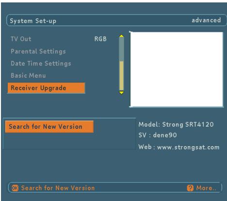
Manual upgrade will start if the 'Search for New Version' button is pressed. Or you can exit by pressing menu.
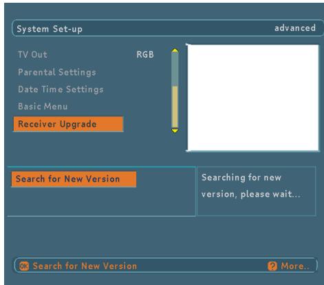
After pressing the 'Search for New Version' button, the STB starts the search procedure and will check if the broadcasted software is newer than its own version. Since this process takes some time, a warning message is displayed.
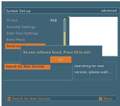
If there is no new software, 'No new software found. Press OK to exit.' message will be shown as below. After pressing OK button, it returns the STB to the system setup menu.
English
If a new software is found, 'Select the Software and the language set' message will be shown.
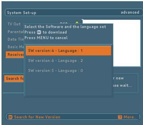
Here software versions and language sets which can be downloaded will be shown.
- Language set 0 means: English, German, French, Italian, Spanish, Polish
- Language set 1 means: English, Hungarian, Romanian, Czech, Slovak, Croatian
- Language set 2 means: English, Dutch, Portuguese, Russian, Turkish, Bulgarian
After user select one of the choices and press OK button, receiver upgrade will start and there will be a message in the screen as below. Or user can exit by pressing MENU button.
If there is no problem during the software upgrade through the air process then the above message indicating a successful upgrade will be shown and the STB will go into standby mode so that changes can take place when it is switched on again.

If subtitle is active, you can not upgrade the receiver because of insufficient resources for subtitle and new software download at the same time. When you try to search for new version, you will encounter a message as below.
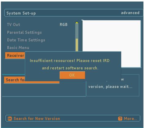
At this situation, you have to reset the STB (IRD) and restart to search in system set-up menu.
While downloading, user can cancel it by pressing MENU button.
Loading the new software, please wait... Or press MENU to cancel.
If the upgrade is cancelled or any error is occurred during the loading process, a warning message is displayed and user is asked to press the SELECT button for returning the last watched channel.
After loading the software into memory(SDRAM), it will be written permanent memory (flash).
If STB power is cut while the downloaded software is being written into the flash memory then the new software will not run since it will not be written completely into permanent memory. The receiver has backup system software that can be restored in such cases. The restoring process is triggered when the STB is switched on afterwards.
7. TROUBLE SHOOTING GUIDE
| Trouble | Possible reasons | What to do |
| No picture or sound. | No signal or weak signal. | Check the LNB and scart connectors and the dish installation. |
| The settings you have done in the menus have not been changed. | The digital set-top box was unplugged without first going to standby. | Before unplugging your digital set-top box, wait for going to standby. |
| The remote control is not working. | The digital set-top box is in standby. | Press the standby key check if nothing blocks the front panel. |
| Remote control is incorrectly aimed. Battery exhausted. | Change the batteries. | |
| You see the on-screen error message related with LNB short-circuit protection mode. | The dish installation is not correct or cable connections have been made incorrect. | Check the connections. If the problem persists, contact with the closest service for help. |
8. TECHNICAL SPECIFICATIONS
8.1. GENERAL CHARACTERISTICS
Supply Voltage : 185 - 265 V AC, 50 - 60 Hz
Nominal Power consumption : 13W
- Power consumption in standby: <7W
- Operating temperature : 5^ to +45^
Storage temperature : -20°C to +70°C
- Humidity : 25 to 75% rel
Physical dimensions : 235× 40× 150mm
Weight : 1.24 kg
8.2.HARDWARE CONFIGURATION
·Main Processor :Sti5518
- Flash Memory : 1 Mbyte
- SDRAM : 8 Mbyte
·EEPROM :128KBit
8.3.DIGITAL CAPABILITIES
Transmission Standards: DVB, MPEG2
i) DEMODULATION
- QPSK with SYMBOL RATE from 2 Msps to 45 Msps.
- FEC for all DVB Modes.(Automatically found)
ii)VIDEO
- All MPEG2 MP@ML formats with up-conversion and filtering to CCIR601 format.
- Aspect Ratio; 4:3, 16:9 with pan vector
iii) AUDIO
MPEG1 Layer 1 and 2
- Sampling frequencies supported are 32, 44.1 & 48 kHz
- Output can be programmed as STEREO, LEFT only or RIGHT only (on both outputs). This is useful for dual mono channels in order to select the correct sound track, which is stored for every channel.
- Wide dynamic range (16-bit resolution)
8.4. REMOTE CONTROL
- Operating Distance
:10mMax.
- Batteries
:2x1.5V Micro (R-03/AAA)
8.5. LNB POWER SUPPLY
Vertical
:13 Volt
Horizontal
:18 Volt
Max. Output Current
: 500mA (Short-circuit protected)
22 kHz Tone
: Frequency 22KHz ± 2KHz
Amplitude 0.6 Vpp ± 0.2 Vpp
8.6.AUDIO R/L
- Connector
:2xRCA (R + L)
Output
: 0.5 Vrms / Z = 1 kΩ
8.7.DIGITAL AUDIO
- Connector
:1×RCA
Output
Digital S/PDIF Output (0-5 V)
8.8.A/V & DATA IN/OUT
Scart
: TV scart, VCR scart
RGB Video Output
:TVscart
CVBS Video Output
:TV scart,VCR scart
CVBS Video Input
: VCR scart
Analog Audio Output
: TV scart, RCA jack, VCR scart
Analog Audio Input
: VCR scart
Digital Audio Output
:RCA jack
Data Interface
: RS 232, integrated into TV SCART Baud Rate 9600 -115200, 10, 12 pin
8.9.SCART (TV, VCR)
- Video output : Composite video signal; 1 Vp-p±3dB/75Ω
- Video input : Composite video signal; 1 Vp-p±3dB/75Ω(for VCR)
- Audio output : 0.5 Vrms / Z = 1kΩ
- Audio input : 0.5Vrms/Z = 10k (for VCR)
- Function switching : 12V / 6V for 4:3 / 16:9 / Z = 10k
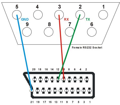
8.10. TV SCART SOCKET
8.11. VCR SCART SOCKET
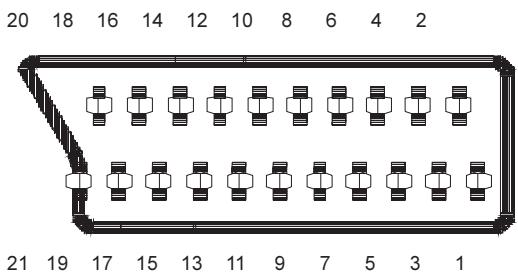
| PIN | SIGNAL | PIN | SIGNAL |
| 1 | Audio Right Output | 12 | TX |
| 2 | No Connection | 13 | GND |
| 3 | Audio Left Output | 14 | GND |
| 4 | GND | 15 | RED Output |
| 5 | GND | 16 | Fast Blanking Output |
| 6 | No Connection | 17 | GND |
| 7 | BLUE Output | 18 | GND |
| 8 | Function Switching Output | 19 | CVBS Output |
| 9 | GND | 20 | No Connection |
| 10 | RX | 21 | GND |
| 11 | GREEN Output |
| PIN | SIGNAL | PIN | SIGNAL |
| 1 | Audio Right Output | 12 | No Connection |
| 2 | Audio Right Input | 13 | GND |
| 3 | Audio Left Output | 14 | GND |
| 4 | GND | 15 | No Connection |
| 5 | GND | 16 | No Connection |
| 6 | Audio Left Input | 17 | GND |
| 7 | No Connection | 18 | GND |
| 8 | Function Switching Input | 19 | CVBS Output |
| 9 | GND | 20 | CVBS Input |
| 10 | No Connection | 21 | GND |
| 11 | No Connection |
9. CONNECTION DIAGRAMS
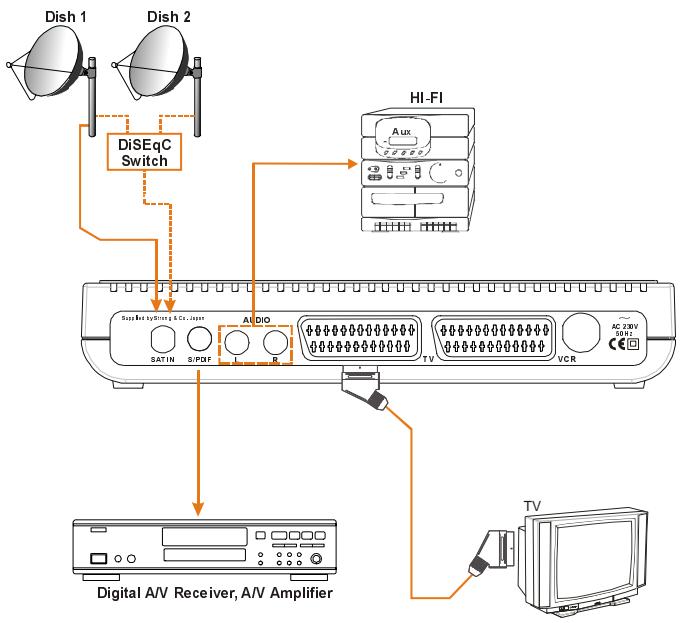
Diagram 1
Diagram 2